The standard AASHTO loads are built into the moving loads database, however you can add and save custom moving loads as well. The moving loads can be applied in any direction, so they can be used to model crane loadings (which are typically applied in 2 or 3 directions at the same location). You can have up to 5,000 moving loads in each model.
Note
To Include a Moving Load in a Load Combination

The Moving Loads Spreadsheet records the moving loads for the
member elements and may be accessed by ![]() Moving Loads on the Spreadsheets menu
Moving Loads on the Spreadsheets menu
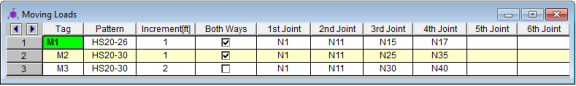
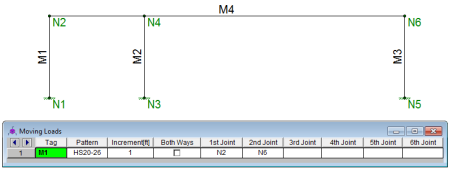
Each moving load definition is automatically assigned a Tag on the left side of the spreadsheet. These labels may not be edited. Moving loads are included in your analysis by referencing this label on the Load Combinations spreadsheet.
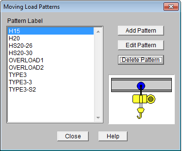
The Pattern field is the name of the moving
load pattern used for that particular moving load definition. You
can access the drop-down list of valid pattern names by clicking the down ![]() arrow in this cell. You may access the
Moving Load Patterns and add or edit your own patterns by clicking on
the
arrow in this cell. You may access the
Moving Load Patterns and add or edit your own patterns by clicking on
the
![]() button
on the RISA Toolbar.
button
on the RISA Toolbar.
The Increment field is the distance that the moving load will be moved for each step in the moving load analysis.
The Both Ways field is a check box that
indicates whether the moving load pattern is to be applied in both directions
of the load path or just one way along
the load path. If the box is checked the load is first run from
the start
The last 10 fields are the
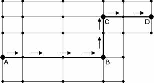
In the example moving load path shown, you would
need to specify
You may access the Moving Load Patterns and add
or edit your own patterns by clicking on the
![]() button on the RISA Toolbar
button on the RISA Toolbar
The file that the moving load pattern database is stored in is ML_LIB32.FIL.
The path to this file is specified in the Application Settings
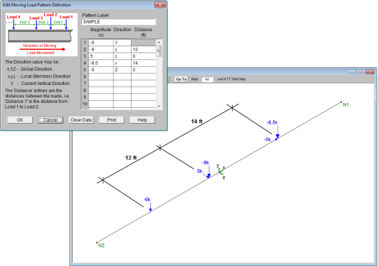
When you add a new pattern, the new pattern must have a unique name and can consist of up to 50 different loads. The sign of the load Magnitude will control which way the load is pointing in the direction specified in the Direction field. The direction field can be any of the 3 global directions or the 3 local directions for the members that the load will travel over. Note that if your load travels over multiple members, a local direction load will be applied based on the local axes of each member it crosses over. There is also a special code, “V”, which causes the load to be applied in the direction of the current vertical axis, whatever it is (X, Y, or Z). The Distance is the distance between the loads.
Note: If you have two loads at the same location but in different directions, you may input them one after the other with a Distance between them of 0 ft/m, as shown in the image below:
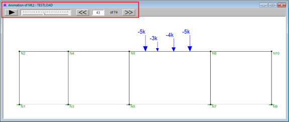
Moving loads are handled internally by applying the loads at discrete locations that are then moved through the model. A static solution is performed for the model at each load location. Typically, once the first solution is solved, the remaining loads are just solved against the existing stiffness matrix, so the stiffness matrix would not be rebuilt for each load position.
Note:
Load combinations that contain a moving load, will step the moving load through the load path and perform a solution for each position. The results are enveloped, giving maximum and minimum results of these solutions.
For these result spreadsheets, the maximum and minimum values are shown for each section location, for each active member. The governing load combination and step location is also shown for each result value under the "LC" column. The first number is the load combination, the second is the step number: (load combination - step number).
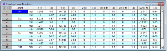
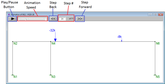
The step location tells you where the moving load was located along the moving load path when the maximum or minimum result value was obtained. This can help you recreate the static model to verify results.
The total number of steps is calculated as follows:

Note
Because solving moving loads produces so much output (full model design at each moving load step increment), the output is limited to Enveloped results. This means that the moving load results only show the maximum and minimum values for each output result value.
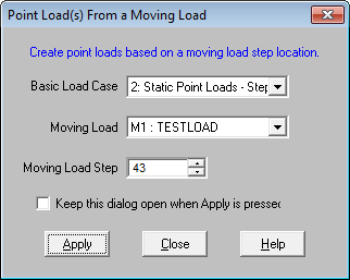
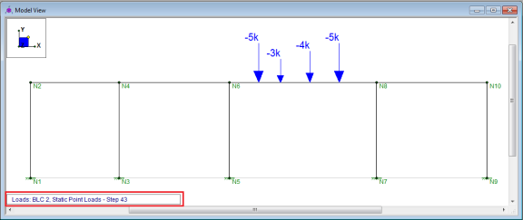
However there are times when you may want to investigate the full model design (all member results, detail reports, deflected shape, etc.) at a specific step. You can easily create a static load case of the moving loads at a specific load step using the Point Loads from a Moving Load feature.
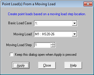
Instructions to use this feature:
 , or from the Insert - Point Load from a Moving Load menu